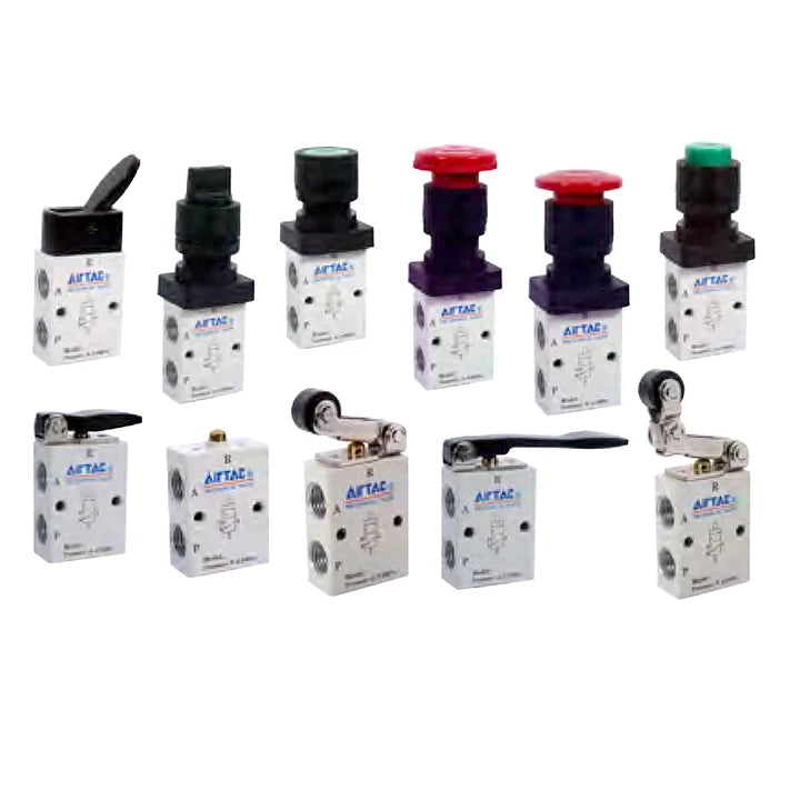

Airtac S3 series: manually operated directional valve - S3DM5
Airtac S3 series: manually operated directional valve - S3DM5
Couldn't load pickup availability
Specifications: S3DM5 is an AirTAC S3 control valve with 3 ports, 2 positions, a short hand lever actuator and M5 × 0.8 connections.
Product Catalog
Download Airtac Product Catalog (PDF)
For detailed product dimensions and mounting drawings, please download and refer to the PDF catalog.
Functional Alternative Statement
Airtac S3 series valves are functional alternatives to SMC VM200 series valves.
Model Code Explained
| Parameter | Details |
|---|---|
| Exact ordering code | S3DM5 |
| Series S3 | 3 ports, 2 positions; external direct mechanical control |
| Control-head code D | Short hand lever |
| Port-size code M5 | M5 × 0.8 |
| Thread option | No thread suffix for the M5 × 0.8 port |
| Color suffix | Not used for this control-head type |
Technical Specifications
| Parameter | Details |
|---|---|
| Fluid | Air, filtered through a 40 μm filter element |
| Operating method | External direct acting |
| Valve function | 3 ports, 2 positions |
| Selected control form | short hand lever |
| Working connection | M5 × 0.8 |
| Effective flow area | 2.5 mm² |
| Cv | 0.14 |
| Operating-pressure range | 0–1.0 MPa (0–145 psi) |
| Proof pressure | 1.5 MPa (215 psi) |
| Working temperature | −20 to 70 °C |
| Body material | Aluminum alloy |
| Lubrication | Not required |
Features and Pneumatic Operation
The shut-off/poppet construction provides internal sealing and sensitive directional switching without a lubrication requirement. The valve supports body mounting and the illustrated panel arrangements for the applicable control head.
The selected control head is manually operated. The available head forms serve different operator controls; only the head encoded in this exact model is selected here.
The catalog identifies this control-head family as using a metal mechanism for durability and stable operation. That statement does not assign an unspecified material to every internal component.
Lubrication is not required. If lubricated air is introduced, continue using the same lubrication medium without interruption; the catalog recommends ISO VG32 oil or an equivalent grade.
Port letters identify P as the supply, A as the controlled outlet and R as exhaust. The graphical symbol in the PDF defines the exact flow paths for the selected actuator and valve position.
Selected Operating Travel
| Parameter | Details |
|---|---|
| Valve-spool stroke | 2.4–3.8 mm |
| Button / roller / handle stroke | 7.4–9.4 mm |
The listed stroke ranges are installation limits for the selected control form. Travel is not an added body dimension. Use the drawing orientation and do not drive the mechanism past its stated range.
Installation, Travel Limits and Operation
Mount the valve through the body fixing points or use the illustrated panel arrangement where the selected head permits it. Keep the body and head aligned and retain access to the pneumatic ports. The catalog does not state a general screw-tightening torque.
Do not exceed the selected spool and actuator stroke ranges. Excess travel imposed by the external mechanism can cause leakage or damage. Engineering-plastic button components must be operated by hand and must not be struck with metal tools; the dedicated mechanical roller/plunger models are actuated by their intended external mechanism.
The spring-return symbol and the installation notes identify an automatically returning actuation arrangement. Allow the actuator to return freely after releasing the operating force.
Body and Mounting Dimensions
The S3B body drawing supplies the base dimensions for the selected port size. A selected control head is shown separately; its dimensions are not a complete assembled-valve envelope.
| Drawing reference | Value |
|---|---|
| Drawing dimension A | 26 mm |
| Drawing dimension B | 16.5 mm |
| Drawing dimension C | 36 mm |
| Drawing dimension D | 30 mm |
| Drawing dimension KA | 16 mm |
| Drawing dimension KB | 15 mm |
| Drawing dimension PA | 13 mm |
| Drawing dimension PB | 9 mm |
| Drawing K | M5 × 0.8; the illustration marks two K mounting positions |
| Drawing P — two connection callouts | M5 × 0.8 |
Selected Control Head and Replacement Reference
The values below describe the selected actuator or control-head assembly. They are separate from the body drawing and must not be added indiscriminately to the body dimensions.
| Control-head drawing reference | Value |
|---|---|
| Side length reference | 43.5 mm |
| Plan length reference | 44.5 mm |
| Mounting longitudinal span | 30.5 mm |
| Handle width | 16 mm |
The S3 catalog explicitly lists control-head assembly M3D210-P13A for this head family. The M3/S3 prefix on a shared replacement head is retained exactly; it does not change this valve’s S3 ordering code. This valve includes its selected actuator; a second head is not required for normal operation.
Dimension Drawing Reminder
All linear drawing values above are in millimeters unless a thread or angle unit is stated. The original drawings retain the dimension-arrow relationships, actuator orientations and port views that cannot be fully represented by a two-column table.
For detailed product dimensions and mounting drawings, please download and refer to the PDF catalog.
Internal Components — Catalog Reference
The sectioned illustration is labeled S3PM. Its numbered components are listed below as a series construction reference. This is not a spare-parts kit or an assertion that every actuator variation has an identical exploded assembly. Materials are stated only where the catalog expressly supplies them.
| Drawing item | Component |
|---|---|
| 1 | Body |
| 2 | Bottom cover |
| 3 | Stopper plug |
| 4 | Valve core |
| 5 | Cross-head screw |
| 6 | Button pressing buckle |
| 7 | Spring |
| 8 | Clamping washer |
| 9 | Dust cover |
| 10 | Button cap |
| 11 | Main button body |
| 12 | Top cover |
| 13 | Button retaining ring |
| 14 | Clamping nut |
| 15 | Button holder |
| 16 | Button fixing connector |
| 17 | O-ring |
| 18 | Spring |
| 19 | Spring |
| 20 | O-ring |
Flow Characteristics
The catalog flow chart for S3B-M5 plots operating pressure in MPa on the vertical axis from 0 to 0.8, and flow in L/min on the horizontal axis from 0 to 300. The family of curves illustrates the pressure/flow relationship. Axis limits are graph bounds, not guaranteed rated flow values for this complete valve; use the supplied curve and the required pressure conditions.
Supply Scope and Related Heads
This ordering code identifies one valve with its selected control-head form. It does not encode a multiple-valve assembly, a spare head, a silencer, mounting-panel hardware or pneumatic tubing. Where the catalog lists a separately orderable head, its exact code is given above as a replacement reference; the source does not provide a screw/gasket quantity breakdown for a service kit.
Series Ordering Options
The S3 family offers B, C, D, Y, R, L and V heads; red-only PL; and PP, PF, PM and HS in red, green or black. Port options are M5, 06 (1/8 inch) and 08 (1/4 inch). The original linked ordering chart uses M5 for the metric complete-valve code, while some replacement-head and Chinese drawing labels use 05; those labels do not authorize changing this listing code.
For 1/8 and 1/4 inch connections, a blank thread suffix means PT, G means G thread and T means NPT. M5 connections have no such thread suffix. These are series alternatives; the selected configuration is the one decoded above.
Reference Weight
Catalog reference weight: 80 g, from the S3D row of the 2022 comprehensive catalog weight table (paper page 300). The catalog weight table identifies the control-head family without a port, color or thread suffix. This is that published family reference, not an independently measured weight for every option. The table states that weights are for reference only; actual weight is determined by the delivered product. This is not a measured or packaged shipping weight.
Catalog Basis
Technical information is taken from the linked S3 catalog and cross-checked against the 2022 comprehensive catalog, paper pages 140–142 (PDF pages 141–143). The paper-page-300 weight table is cited separately above. No unrelated series dimensions or weights are substituted.
Product features
Product features
Materials and care
Materials and care
Merchandising tips
Merchandising tips
Share